Maintenance/Upgrade:
After 11+ years of high underhood temperatures, the
original Fuel Injection
wiring harness and the AMP electrical connectors
that snap onto the Fuel Injectors had become brittle
on my 1989 XJ-S V12.
At some point, this needed replacement,
however, the real impetus for making this change started with
an incident that could have been a disaster.
My wake up call came one day when
the car started losing power and backfiring like a cannon.
This had happened a couple of times to a lesser
degree before, but "mysteriously"
cleared itself up.
This time, power dropped off to nothing and
a whiff of smoke seeped from under the bonnet. Oh No!
If you have had this happen with your car, you may be having
the same problem so read on.
Immediately stopping the car and opening
the hood, the (USA) drivers side catalytic converter was glowing
a bright yellow-red!
Later I was to find that one or more of the Fuel Injector
Electrical Connectors had come loose,
an injector(s) wasn't firing, and as a result, the ECU
saw the B bank go lean and increased more fuel to the other cylinders. The
excess fuel came out the exhaust manifold and was burning in the cat. This
is one way underhood fires can begin in an XJ-S.
Getting the car back to the house for examination,
it was running rough on the "B" bank.
By unplugging one injector connector at a time, it was easy
to determine which injector was not firing as removal made no
difference in engine roughness.
Curiously, desptite the AMP electrical connector to the injector feeling
like it was snapping
onto the injector, the problem did not
always clear up. Therefore, that connector's
inablity to always make a solid connection to the injector
was suspect. Replacing just the connector would be penny
wise but pound foolish.
A new harness would be expensive. The Jaguar dealer wanted around $1,200 USD
and prices on the Internet ranged from $850-$1100. However reports
of other XJ-S owners on the Jag-Lovers.org XJ-S "list"
had reported making their own harnesses
for substantially less. The project was worth investigating, and could
also be fun and save a lot of money too.
For fans of this web site, you know that I also seek form
to follow function, so there was a second motivation for making
my own harness. After giving it some thought,
I realized it was possible to hide this wire loom out of
sight and also protect it from prolonged
subjection to extreme underhood temperatures.
First, a little background on the configuration of
the stock fuel injector harness.
All the wiring for the fuel injectors
comes from the Engine Control Unit in the trunk (ECU)
through the passenger side firewall (U.S. version cars) to a wiring bundle
running along the top of the right wheel well, terminating
in an eight pin female connector. There, an
eight male connector plug that terminates the loom of wires up
into the vee of the engine
connects to a female plug.
This connection point is
hard to see by casual observation because the air cleaner assembly is
slightly in the way. Yes, that's it--the dull yellow white plug
covered in oil and gunk.
From this connector, the loom runs underneath the air conditioning compressor,
under the bellows-like cruise control sitting on the front center
of the Vee of the engine, and up to the left and right banks to
each injector.
In a stock XJ-S, most of this would be hidden out of sight, but with my
engine beautification project,
I did not want these wires to continue to be exposed.
Also, continuing to let wire lay
on top of the vee of the block cooking in the center of the engine
did not seem like a good idea.
My solution was to
double back the wires for the new harness
from the main connector plug
along the right fender well
and the firewall to feed through the back of the vee
of the engine.
In addition to the visual aesthetics in doing so, it would
reduce the amount of heat that
the harness would be exposed to over time.
These types of changes, while appearing easy, never are,
as other unforeseen details always
pop up, complicating the project.
One was the direction that the F.I. electrical connectors were pointing.
Cylinders are numbered from front to back (i.e.
1 through 6). Cylinders 1, 2, and 3 had connectors pointing towards
the front of the engine, but the back three connectors
were pointing towards
the back (firewall.) Interesting, odd, and unacceptable.
I decided to change all the injector connectors to face
towards the back (firewall) since that's from whence the new harness
wires would come. However this by neccessity demanded a whole
other project with removal of the fuel rail,
injectors, and
replacement of the Fuel Injection hoses.
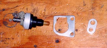
The reason is that the hold down plates for
the injectors are keyed to point either forward or
backward. They can not be switched around without cutting/removing
the FI hose. (See the notch in the picture below and how it fits
in with one side of the injector):
 Steps to Rebuilding the FI Harness
 After disconnecting and
removing the old harness, start with cutting off the main
8-plug connector. Leave enough wire to work with and strip
the ends so that later these ends can be melded into the new
wiring of the harness. This plug is
probably filthy dirty with oil and
dirt and a good washing
in Dawn Dishwashing Detergent will
clean it up to an off white color.
After disconnecting and
removing the old harness, start with cutting off the main
8-plug connector. Leave enough wire to work with and strip
the ends so that later these ends can be melded into the new
wiring of the harness. This plug is
probably filthy dirty with oil and
dirt and a good washing
in Dawn Dishwashing Detergent will
clean it up to an off white color.
Purchase new Wire
The local Napa Auto Parts store had
plenty of colored "hook up" wire available in several colors
(an important consideration as you will see.) The colors
you will need are listed below. Although not
"high temperature" the box said it was good up to over
220° F. Considering that the new route took it out of the arduous conditions
of the center vee, this seemed reasonable replacement and
at least on par with the original wire. I also upgraded the gauge
thickness from the standard 18 gauge to 16 gauge for a more solid
electrical signal to the injectors. I also did this because of the way
I would change the stock configuration and "tap" onto each wire (details below.)
Buy New AMP Connectors
 Sourcing the replacement AMP (brand) connectors was a bit more difficult.
I tried looking on the Internet for many
hours without luck searching auto parts dealers, the AMP site,
auto electrical supply sites for "Jaguar XJ-S" "V12" and the like,
and by using the cryptic numbers stamped on
the side of the injectors to no avail.
The local NAPA Parts guy swore that he had seen injectors
and the associated AMP connectors like
the Jag V12's before on another car, but without a part number,
it was a shot in the dark to locate it.
Sourcing the replacement AMP (brand) connectors was a bit more difficult.
I tried looking on the Internet for many
hours without luck searching auto parts dealers, the AMP site,
auto electrical supply sites for "Jaguar XJ-S" "V12" and the like,
and by using the cryptic numbers stamped on
the side of the injectors to no avail.
The local NAPA Parts guy swore that he had seen injectors
and the associated AMP connectors like
the Jag V12's before on another car, but without a part number,
it was a shot in the dark to locate it.
Yet again, fellow Jaguar owners, this is simply a
car, not some sacro sanct special piece of equipment
available no where else on the planet. Parts come from general auto sources,
not just Coventry.
To add insult to injury, my counterman went onto say
that this "standard" AMP connector
and the actual injector are about 60% less if listed for
a non-Jaguar. This was half right.
According to fellow Jaguar enthusiast Ed Sowell,
the NAPA part number is 2-17411 and costs only $1.35 USD.
(see Ed's injector rebuild notes at
http://home.adelphia.net/~sowelled/ed/engine/injharness/harnessindex.htm)
I wish I knew this before plunking down over 10 times more
for the "real" Jag part. At least mine has matching rubber
boots and new 1A, 3C type tags for each cylinder--a hefty
premium for what I paid.
If you own a Jaguar, you know the drill. They see you
coming and dollar signs appear in their eyes.
I finally had to resort to calling Jaguar vendors.
I am ashamed to write I can't remember the vendor(s) I got them
from, but they are available, although many Jag suppliers had to be called
before finding one that carried the item.
A set of 12 cost around $100. Be sure the set you get includes the
rubber boots that slip over the plastic connector and the numbered
cylinder rings. For that kind of money--they better.
The parts numbers are:
- AMP Fuel injection Electrical Connector: Part # 15M99031
- Fuel injection Boot Cover: Part # 15M99021
Determining The Wiring Configuration
 With the wire and connectors in hand,
it was time to start the project.
In removing the old harness--and I'm exageratting here--it was so
stiff and brittle, you could almost hold it up sideways
and have it stick straight out, looking a little like a Charlie
Brown Christmas tree.
With the wire and connectors in hand,
it was time to start the project.
In removing the old harness--and I'm exageratting here--it was so
stiff and brittle, you could almost hold it up sideways
and have it stick straight out, looking a little like a Charlie
Brown Christmas tree.
After removing the harness, an exacto knife cut away the
now hardened outer sheath.
The big surprise was that each bank (6 cylinders) used only four wires,
thus, twelve cylinders were "fed" by only eight wires.
Interesting. After cutting open and documenting the stock F.I. wire
harness, it all made sense.
Each side of the engine ("A" and "B" bank) has two sets of wiring connections that
tie into three alternating cylinders. One set handles cylinders 1/3/5 and the other
2/4/6. Since each side has only four wires to "feed" six cylinders, it was
becoming clear that some of these had to be wired in tandem.
Each bank has two (for lack of a better term) "ground" wires (see below chart
and diagram.) One ground is shared
with 1/3/5 and the other with 2/4/6. Each ground wire is the same color
code (pink/black on my 1989 Marelli car). The other two wires are distinct colors
per side. Here is the breakdown of how they are wired:
| Cylinder Bank Side |
Connects to Cylinders |
Color |
| A |
1/3/5 |
Orange/Blue,
Pink/Black(i) |
A |
2/4/6 |
Orange/White,
Pink/Black(ii) |
| |
| B |
1/3/5 |
Orange/Slate,
Pink/Black(i) |
B |
2/4/6 |
Orange/Green,
Pink/Black(ii) |
Eight (female) pins from the harness to the injectors
plug into the
main male connector plug. The following diagram documents how
each of these eight male connectors routes to the corresponding
cylinders. This view is looking into
the male plug, i.e. the connector going to the injectors.
[Note: The black
dot is a rubber dummy male plug and is not wired and the lower left location
is vacant:]
 Logistics and Wiring Things Together
As there are four wires per bank of the engine (A and B sides), I used
cable ties to bind these small wire bundles together.
I even labeled each four wire bundle with a piece of
paper "A" and "B" so that when referencing my cheat sheet, I knew
I was working with the right wire on the correct cylinder.
The last thing I would want to do is go through all this work, put
it in the car for it to be wrong.
 Each of
the four wires is connected in tandem to three cylinders. In the original harness,
this was handled by running one wire to come up to a point right before
the front most cylinder
and stopping. [See Picture Here]
From there, three other wire points met it, continuing on to each respective cylinder.
So in essence, the same wire was being double run up past most of the cylinders!
This made for a bulkier set of wiring.
Each of
the four wires is connected in tandem to three cylinders. In the original harness,
this was handled by running one wire to come up to a point right before
the front most cylinder
and stopping. [See Picture Here]
From there, three other wire points met it, continuing on to each respective cylinder.
So in essence, the same wire was being double run up past most of the cylinders!
This made for a bulkier set of wiring.
In my harness, I ran just one wire down past each
of the injectors and tapped into the wire as it passes each AMP connector.
Using the now removed
fuel rail as a measuring stick for spacing,
I stripped the wire sheathing about ¾ inches where the wire passed the injector.
From there, I took one of the
the AMP connector (white wires--see previous picture or
right click here for pic)
and tapped it onto
the new loom wire by first weaving it firmly around the exposed wire,
securing it with some solder, then wrapping that tightly with electrical tape.
Here is a rough diagram
of my "tee" connector:

Using six different colored "hook up"
wires make it easier to keep track of what was what
by color coding them to the stock wire as follows:
NEW ORIGINAL COLOR
Pink = Pink/Black (i)
Black = Pink/BLACK (ii)
Orange = ORANGE/White
Blue = Orange/BLUE
Green = Orange/GREEN
Slate = Orange/SLATE
Having the wires color coded made things a lot easier. Using the wire/cylinder
correlations above, and also working with similar colored wire helped
to see which wires on each bank connected to each F.I. connector.
Remember that if you chose to re-route the loom as described
here, the wire runs will be much longer, and this needs to be
taken into account when creating your new F.I. loom.
The initial plan was to cut all the wire runs to be just long enough
to meet at the main connector plug and connect all eight
wires to the 8 connector male plug.
This proved impratical for
several reasons. For one, I kept messing up portions of wire and had to cut
off pieces and start over. Second, in order
to keep the "A" and "B" side wires sorted out on the work bench
and for neatness in all these strands meeting at the main connector, it was
apparent that it was easier to do all the splicing and wiring
by the AMP connectors first, then take all eight wire ends and
slip on the heat shrink tubing last as the main connector was
braided into the new wiring.
Once all eight wires were
soldered securely, I then bound the
four wires per bank in separate heat shrink tubing for
both neatness and identification purposes.
This way I could tell if I was working on the "A" or "B" bank wiring. For extra protection, I then slipped
an even larger shrink tubing to cover up all eight wires where it butted up against the main connector.
I did not bother using a hair dryer to shrink the wires;
the engine did a good job of that just driving around a day or so.
Now it was time to connect the AMP units into the loom for the "A" and "B" banks.
The wires that are attached to the AMP unit are quite long--long
enough to attach to the colored hook up
wire where the harness would be running from the back to
the front of the engine. In many cases when
the same wire would be continuing pass a cylinder forward,
I simply cut away about a 1/2" portion of the
wire cover right at the vicinity of the injector, then
took the appropriate white wire coming out
of the AMP and wrapped/tied it onto the copper wire.
I put a little sodder
on for good measure, then neatly wrapped it in electrical tape.
The connectors were essentially
'tapped' onto the appropriate wire for that cylinder.
The end result: The harness laid much much
more naturally in the engine and was much less bulky.
One small but potentially important note. If you look at the original and new AMP
connectors you'll notice that one white wire comes out the 'left' side of the top
of the unit, the other the 'right' side; depending how you hold it.
Look carefully and you will see a small "+" symbol
on one side of the injector. Connect that to the power
wire and the other side to the ground.
You certainly didn't want to go through all this and have it not work.
Final Steps
Once all of the AMP units were wired in, I used a (black)
wire loom cover to cover the exposed
colored hook-up wire. These wire covers are inexpensive, comes in
different sizes for different thichnesses
of wiring to cover, and are readily available at most
auto parts stores.
|
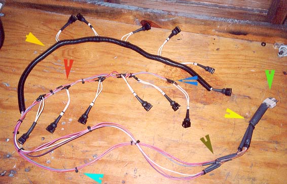
Wire Loom Picture and Legend
|
|
BRIGHT GREEN: 8 pin male main harness connector
YELLOW: Shrink wrap tubing
KAKHI GREEN: More shrink wrap tubing
TURQUIOSE: Cable tie to bind strands together
RED: "Tee" connection tapping into wire
BLUE: Extension to forward (#1) cylinder
GOLD: FLexible coil split wire sheath covering
|
Conclusion
The result, as you can see , is a fresh, custom wired F.I. wiring
harness that has improved the appearance of the engine compartmetn and should easily last
another 10-15 years. The project is fun, low costy, and easy to do,
just requiring time, patience, and a place to work. Total expenditure
was modest and significantly less than buying a replacement
harness:
5 rolls or wire @ $6.45 a roll = $32.25
1 Dozen AMP FI Connectors = $112
1 wire loom package, ½" diameter = $4.00
1 wire loom package, ¾" diameter = $4.00
TOTAL = $152.25 USD
I hope that this article has helped you with your Jaguar, and if so, would you
please sign my
Guest Book and let me know? Thank You.

![[See Picture Here]](./images/fi-orig-loom-dbl-back-wires.jpg)