Note: There are lots of on this page, but be
patient, they are worth downloading without hitting STOP!
|
This page is dedicated to my father, who
I admired as a little boy "helping" him in his
old Flying "A" service station. Dad, I learned so
much from you, and this project is dedicated to you.
|
It all started innocently enough. I decided to purchase the
AJ6 "Torque Plus" kit (tuned intake manifolds),
their larger throttle bodies (shown here)
and enhanced ECU. The last two parts were
a simple two hour procedure. However, those tuned
intake runners (which increase torque up to 50 lbs to the engine)
required a lot more work to install and I knew it.

I stared at the engine a long time. I read and re-read the
shop manual and carefully planned what I thought I might do.
It was quickly apparent this would not be
something that I (as a simple shade tree mechanic) was going to easily do in
one weekend! Being the procrastinator that I am, I decided to
shelve the project until I had the
time, energy, and courage to undertake the task.
After a month of sitting on my hands, thinking about
what I wanted to do, and staring at the "new" intake manifolds,
things became clear.
"Why go through all the trouble of installing a 'new'
intake manifold if it looks just like the old one?", I reasoned.
There had to be a creative way to do something with this part and
make the effort of installing this performance piece, and
have form follow with function.
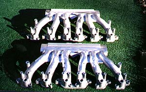
So I began to work on improving the the appearance of the intake
manifold. As you know, the XJ-S intake manifold is a fairly
rough, cast piece of aluminium.
It is silvery, but not
really shiny, nor terribly attractive right from the factory.
And like the rest of the Jaguar V-12 engine--which
is an impressive power plant--it is not very pretty.
That's when my creative juices started to flow.
What if the
V-12 could be made to have a 'show quality' appearance?
What would it take? What improvements could I make that would be
fitting in the style of Sir William and of Jaguar Cars??
And thus began this project to create an engine that would be
fitting of the name JAGUAR.
With the intake manifolds so prominent a part of the under hood of
the engine, it looked like the best place to start.
The intake manifolds were the key focal point of theentire project.
I decided that it was worth a try to smooth out the surface and see if I
could bring out a shiny luster to the rough cast aluminium surface.
Working with my hand held grinder and some aggressive
 brillo-type pads, I worked on a
couple of test spots at the intake (throttle body) side of the
square plenum inputs in an experiment to try smoothing out the rough
cast metal. A little success! It looked promising that
the metal could be smoothed and eventually polished, liberating the
brilliant shine inherent deep within this ugly sandcast
piece. I then started on the intake runners themselves.
brillo-type pads, I worked on a
couple of test spots at the intake (throttle body) side of the
square plenum inputs in an experiment to try smoothing out the rough
cast metal. A little success! It looked promising that
the metal could be smoothed and eventually polished, liberating the
brilliant shine inherent deep within this ugly sandcast
piece. I then started on the intake runners themselves.
Here was the first set back. These curved, tubular pieces
would prove extremely difficult to get as smooth and shiny as
the flat parts of the intake plenum. It appeared
to be a hopeless cause--at least with the simple tools
at hand, so a plan "B" had to be developed.
That plan was to smooth out the intake runner inlet tubes so that
they could later be painted by removing the flashing marks and other
gross surface impurities of the rough factory casting. This was
a more realistic goal.
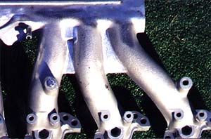
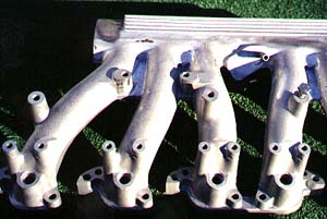 Neccessity is the Mother of Invention, as the saying goes, and
a problem became very apparent. The intake runners have several screw 'towers' that
stick straight up out of the individual runners. On my 1989 model,
almost all of these were not being used (unlike earlier
Lucas cars which had a variety of parts attached to the intake manifold).
The towers were in the way of getting the tools close in enough
to smooth many of the spots between the 'fingers' of each cylinder's input
tube to do the detail work required. Next was to determine
which of these screw towers was
really necessary. Happily, most
of them were unused on the Marelli cars (1989-on) and all
of them could be removed except for the far left and right protrusions.
Neccessity is the Mother of Invention, as the saying goes, and
a problem became very apparent. The intake runners have several screw 'towers' that
stick straight up out of the individual runners. On my 1989 model,
almost all of these were not being used (unlike earlier
Lucas cars which had a variety of parts attached to the intake manifold).
The towers were in the way of getting the tools close in enough
to smooth many of the spots between the 'fingers' of each cylinder's input
tube to do the detail work required. Next was to determine
which of these screw towers was
really necessary. Happily, most
of them were unused on the Marelli cars (1989-on) and all
of them could be removed except for the far left and right protrusions.
Using the grinding wheel on a bench grinder, it was fairly
easy to wear down the unneeded towers. When getting down to each inlet
finger, it was visually important to not destroy the radial of
each finger, so for this delicate close in work, it was
required to switch over to the hand grinder. Working patiently,
I was eventually able to radius each finger out perfectly, just as if
the huge metal screw towers were never there! I love it when a plan comes together...
I even ground out what appeared to be the input mold points between
the fingers where it meets the plenum. There is a little webbing
there that had a cast "O" ring in the metal--both ugly and obvious.
Working with a hand drill and lots of grinding bits, I smoothed
these details off too. My obsession with detail was now snowballing.
The crossover vacuum tube visuall appeared to be yet
another unnecessary clutter point too, so I decided
(after running the car with the tube off and the holes plugged up to
test if it effected running/performance of the engine) to
remove it. The car was actually running (it seemed?) a little better,
without the tube, so it's associated holes and fittings on the inside of each
intake was ground down and smoothed out. Where the crossover tube
meets the intake manifolds is an unsightly great glob of
metal between the front three and back three intake tubes in the middle
of the manifold. This also was trimmed up by carefully smoothing out and
grinding as well.
Now each intake manifold was starting to take shape. The surfaces were
even, camfered, radiused, and finally, the triangular plenum was buffed
to a mirror like shine. It was starting to look beautiful.
 About this time, I was visiting my friend David Laughton in Urbanna,
Virginia. David owns
Coventry Classic Cars, specializing
in rare and unusual Jaguar parts from SS-100 through modern Jaguars.
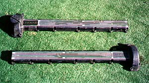
I saw in his parts shop a pair of the older style XK-E V-12
cam covers--the ones with the nice flattened ribbing. These are much
more attractive then the stock XJ-S pointed rib covers. I bought
a set for $50 USD with the idea that, detailed right, these could
also enhance the goals of this project.
About this time, I was visiting my friend David Laughton in Urbanna,
Virginia. David owns
Coventry Classic Cars, specializing
in rare and unusual Jaguar parts from SS-100 through modern Jaguars.
I saw in his parts shop a pair of the older style XK-E V-12
cam covers--the ones with the nice flattened ribbing. These are much
more attractive then the stock XJ-S pointed rib covers. I bought
a set for $50 USD with the idea that, detailed right, these could
also enhance the goals of this project.
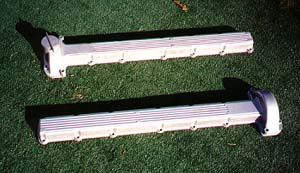 After having the cam covers bead blasted to strip off the old paint,
polishing and detailing of the cam covers begun.
At first, the plan was to polish the whole cover--much like the older XK
and early XK-E engines. But like my experiences with the intake,
the many small bends and nooks on each cover
meant I'd be into this much more time
than I was willing to give. I instead concentrated on
removing the (surprising) number of
After having the cam covers bead blasted to strip off the old paint,
polishing and detailing of the cam covers begun.
At first, the plan was to polish the whole cover--much like the older XK
and early XK-E engines. But like my experiences with the intake,
the many small bends and nooks on each cover
meant I'd be into this much more time
than I was willing to give. I instead concentrated on
removing the (surprising) number of
 uneven casting blemishes that were hidden so nicely
beneath the factory black paint.
The curved tops (over the cam gears) and the flat surface
of the cover to a high luster were left to high luster polishing,
yielding a gorgeous chrome-like finish.
The rest of each cam cover was painted a
Jaguar gold in the tradition of the heads on the E-type.
A dab of PB Weld was added to the back of
a round brass Jaguar logo from
a couple of dealer purchased key fobs
for an extra special finishing touch.
uneven casting blemishes that were hidden so nicely
beneath the factory black paint.
The curved tops (over the cam gears) and the flat surface
of the cover to a high luster were left to high luster polishing,
yielding a gorgeous chrome-like finish.
The rest of each cam cover was painted a
Jaguar gold in the tradition of the heads on the E-type.
A dab of PB Weld was added to the back of
a round brass Jaguar logo from
a couple of dealer purchased key fobs
for an extra special finishing touch.
All in all, between 50 and 60 hours labor
went into the two cam covers and
intake manifolds alone. I was happy with the results, but knew
that a poor paint job would ruin everything for which I
had worked so hard. Therefore,
the painting would have to be a specialized step that must be done correctly
to achieve the desired effect. Although I briefly
considered buying a powder coating kit from
Eastwood Catalog I eventually decided
against it. This was a job for professionals.
With both the cam covers and intake manifolds cleaned, smoothed, and polished,
I took these four pieces to a local powder coating specialist. After
four weeks, I got the pieces back--and they were better than I had hoped.
The black and polished aluminium of the intake manifolds were a perfect
complement to the polished parts of the cam covers with their gold paint.

The next step was of course to install these pieces. According to
the Jaguar "Repair and Operations" Manual (ROM), this is a ten
to twelve hour job. That is not too bad, but then I came to grips
to what I really was looking for--that being an exquistely detailed engine.
What I knew I wanted to do was to polish, laquer, and paint every nut and bolt
in the engine compartment. This turned out to be a non trivial task!!
I clearly underestimated the time it would take to disassemble, label,
clean, polish or paint and reinstall all of these pieces. We are
talking hours, and hours, and Hours of polishing individual
nuts and bolts. It seemed like I'd never get done.
What I decided to do to save time was go to the hardware store and buy
new replacement bolts. I reasoned that it would be much easier to
polish and install these then to resurrect the gummed up old hardware.
This proved to be a huge time waster then time saver. Despite the
best efforts of my local hardware store, invariably I'd wind up
with an incomplete assortment of incorrect sizes. I found this out
the hard way when, after carefully polishing them, they often would not fit
as replacement bolts or nuts!! The moral of the story--even the best
hardware stores have boxes of inventory that have different pieces mixed in.
Be sure that all the pieces you get are the same before
you leave the store. Insist upon it.
 I've mentioned the laquer and painting. Here's what I did and why. The
Eastwood Company offers a clear high
temperatures up to 400 degrees F. I used this to coat all my bolts because
I knew after polishing, they would get dull over time if unprotected.
I also used engine paint to enhance certain pieces. This is great stuff,
but be careful not to put it on to thickly. It will turn cloudy if
you do.
I've mentioned the laquer and painting. Here's what I did and why. The
Eastwood Company offers a clear high
temperatures up to 400 degrees F. I used this to coat all my bolts because
I knew after polishing, they would get dull over time if unprotected.
I also used engine paint to enhance certain pieces. This is great stuff,
but be careful not to put it on to thickly. It will turn cloudy if
you do.
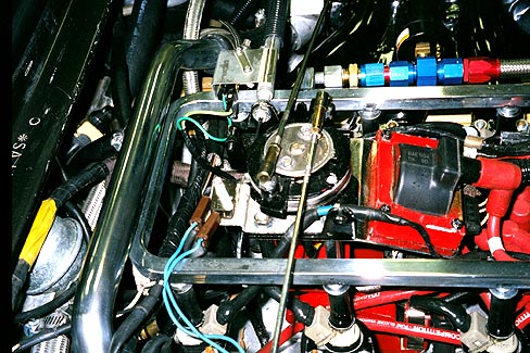
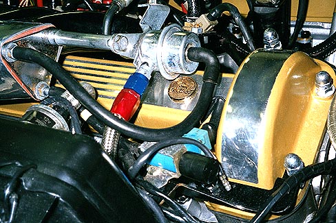
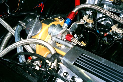
The Vee of the engine
was repainted in silver, the throttle tower in red, and miscellaneous
small parts in black. All of the head bolts, including those lovely
'acorn' bolts were polished to a high chrome-like luster and lacquered.
The two throttle linkage assemblies in particular came out very nice, with
the rods a gleaming chrome with brass tips and the linkage a shiny chrome like
luster. The triangular butterfly shaft rods that mount to the intake manifold I painted black.
All of this required a tremendous amount of careful masking to avoid
overspray onto the shiny metal pieces of each shaft (where it connects into the side
of the throttle body). I was more than pleasantly surprised with how smooth the black engine
paint looked on these painted parts.
Not as good as the powder coating, but very
professional looking, nonetheless.
Installation was the next step. I carefully had labeled all the parts upon disassembly, placing
all parts into baggies and identifying
not only what they were but where they were
mounted into the engine bay. Reinstalling
was not easy, but it was not hard--there were just a lot of parts!
Once everything was stripped off the car,
I started with the center of the vee. First I removed all the head
bolts and other hardware and throughly
cleaned and washed the top of the vee of grease and dirt even
I could not get out with my extensive
Engine Detailing Tips. In
doing so, I had to figure out
a way to keep water and debris from going into the now exposed inlet
ports (as I had removed the old intake manifold to better clean the engine).
I found that a dozen 1 1/14"
rubber bathtub plugs at just 77 cents each at K-Mart worked beautifully.
After everything was clean and dry, I masked off all the exposed head
threads, and used the old intake gaskets wrapped in masking tape
to protect the intake ports and surrounding metal from paint overspray.
I papered and tape mased off the front (cooling pipes and all FI wires)
and firewall area too.
I also left the old sparkplugs in too and just painted over them--
they were going to be replaced and it was convenient to leave
them in during the painting.
I then spray painted the center vee in high temperature
aluminium colored engine paint. I
left the old cam covers on so that I could paint up to the edge
of the covers on the block without concern of painting the
cam shafts underneath. It took two good coats over two days to
provide the paint time to dry and cure.

Next, I carefully removed the old plugs, making sure to throughly
clean each plug thread while I had unrestricted access to the engine.
Then I installed the Bosch Platinium+4 plugs with a little dab
of anti-sieze so the steel plugs would be easy to remove
from the aluminium heads next time and not
get stuck in the future (by the way, the old plugs came out very easily).
In went a new Marelli distributor cap and rotor with
 new Marelli replacement parts.
The vacuum twin rubber lines into the distributor
were upgraded to braided steel for looks and durability.
I decided to replace the original spark plug
wires with high performance Magnecor wires. The brilliant red
silicon sheathing makes a dramatic statement when combined with
the newly painted red throttle tower and spark coils. If a part was not
painted, it was polished down to each screw, nut and washer to
a chrome like finish.
So everything in the engine center is now clean and shiny.
new Marelli replacement parts.
The vacuum twin rubber lines into the distributor
were upgraded to braided steel for looks and durability.
I decided to replace the original spark plug
wires with high performance Magnecor wires. The brilliant red
silicon sheathing makes a dramatic statement when combined with
the newly painted red throttle tower and spark coils. If a part was not
painted, it was polished down to each screw, nut and washer to
a chrome like finish.
So everything in the engine center is now clean and shiny.
The cam covers were relatively easy to install too. The infamous "half moon
seals" were not at all as difficult as I had heard. All they are are two
little rubber seals that are half of a circle which fit between
the cam cover and the head at the firewall end of the cam covers.
 I torqued them down to the factory spec of 14 lb/ft. I also added
polished domed cap screws, just like the E-type engine, to the front cam cover
nuts. This helped to make the front cam covers look much nicer
than the stock XJ-S bolts and exposed threads. The other bolts for the
cover I painted in black. They are a nice contrast to the gold of the
cam covers.
I torqued them down to the factory spec of 14 lb/ft. I also added
polished domed cap screws, just like the E-type engine, to the front cam cover
nuts. This helped to make the front cam covers look much nicer
than the stock XJ-S bolts and exposed threads. The other bolts for the
cover I painted in black. They are a nice contrast to the gold of the
cam covers.

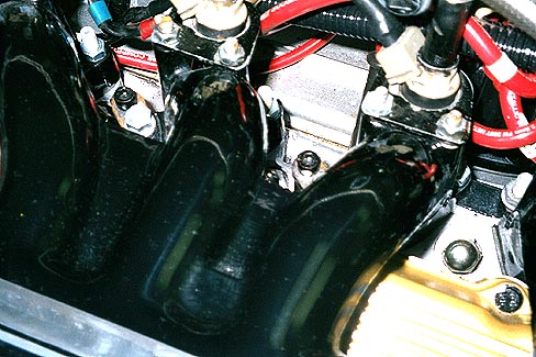
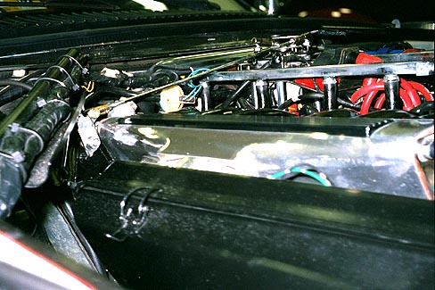
Before installing the newly detailed intake manifolds,
I made another big decision. The air rails seemed to be
an unsightly bit of congestion under the hood, and I had heard of
other XJ-S owners who had successfully removed these without effecting
emmisions. I decided to pull the air pump and not install the
air rails. Instead, I carefully polished the oval shaped spacers
that sit on top of the intake manifold and drilled holes into them.
I then tapped the holes to fit 5/16 x 3/4 Socket Head Cap Screws
which I painted black. These plug into the air intake
ports.
The intake manifold then easily slipped into place. Once
these were in, I was ready to install the fuel rail which I also
buffed out and polished on my bench wheel.
The fuel rail is a little tricky to install. Although some
XJ-Sers recommend putting the intake manifolds and fuel rail
in together as one piece, I would not doing it that way. It is too much to handle
at once, and definately not a job for one pair of hands.
However, instead I put the rubber washers that goes around each injector nozzle
in the indented holes on the intake manifiold first and
then pressed the fuel
injection nozzles through these into the manifold. I found this to be easier than
putting the seals on the injectors and trying to get them to
seat in the intake manifolds. I had to do this twice before I succeeded.
One key is to begin tightening the screw down bolts from the center
cylinders outward--not front to back. They will seat better if you do.
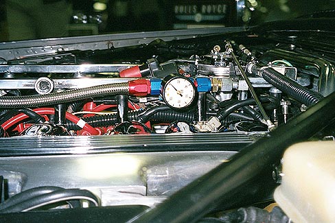 I also decided to replace the stock fuel lines with Aeroquip
racing quality braided steel hoses and to add an inline fuel pressure gauge
off of the fuel injection rail. Next to grinding and polishing the
cam covers and manifolds, this took the most time in the project, and
I learned a lot from the experience. Here's why...
I also decided to replace the stock fuel lines with Aeroquip
racing quality braided steel hoses and to add an inline fuel pressure gauge
off of the fuel injection rail. Next to grinding and polishing the
cam covers and manifolds, this took the most time in the project, and
I learned a lot from the experience. Here's why...
Braided lines are in "AN" sizes (which stands for Army-Navy)
of AN4, AN6, AN8, etc. (the larger the
number the larger the hose). The XJ-S uses an AN6 sized hose which is
approximately 5/8" inside diameter. All of the Aeroquip
line components are based on the
AN size--not standard British or Metric sizes. Now the hard part.
The connector at the fuel rail is a metric 14 millimeter thread
with 1.5 pitch. A male Millimeter to AN adapter is needed to connect
to the Aeroquip hoses and connectors at the fuel rail. I went to Performance
Plus in Norfolk Virginia (800-752-2927) and worked with the 'parts lady
of parts people', my new "best friend" Joyce. Although
Aeroquip lists this adapter in their catalog, they do not manufacturer
it at this time (!), but Joyce found another supplier in Atlanta
and had the part shipped to me. She also figured out all the
AN adapters I needed as well to plumb the whole thing together.
In essence, you will need 2 male 14mm to AN 6 adapters (which attach
to the fuel rail--Joyce called these the 'crazy adaptors') and
1 female 14mm to AN6 adapter to screw into the
"B" bank side (fuel return) fuel regulator. (This part is
available as Earl's [brand] part # 9894DBH) You also should have
three 90 degree elbows-- a) coming out of the "A" bank fuel regulator
and then another 90 degree turn to go into the right side Fuel
Injection rail, and the third on the return fuel side to make the turn
from the hose down to the other fuel regulator. If you want to put in
the fuel pressure gauge like I did, you'll need a bunch
of other miscellaneous in line connectors and adaptors.
Joyce can set you up--just reference my application. She should have
all the part numbers.
Replacing the intake (from the fuel tank) and the return fuel
lines was not difficult, but it was not easy either. The nipple
 at the firewall termination of each hose is threaded into the hose
and can not be pulled off. You will need to cut it off with
an exacto knife. However be forewarned that the return fuel line
on the drivers (USA) side has pressure feeding bank from the gas
tank, so when you remove this line, either at the pressure
regulator end or firewall, gas will flow profusely, so be prepared to
cap the hose or plug in the new one immediately.
at the firewall termination of each hose is threaded into the hose
and can not be pulled off. You will need to cut it off with
an exacto knife. However be forewarned that the return fuel line
on the drivers (USA) side has pressure feeding bank from the gas
tank, so when you remove this line, either at the pressure
regulator end or firewall, gas will flow profusely, so be prepared to
cap the hose or plug in the new one immediately.
Another significant modification I did was to remove the inline
fuel cooler assembly that sits on top of the left hand air filter for
my 1989 model year car.
I did this for two reasons. One, it looks ugly, and replacing the
standard ugly rubber lines and the metal cooling tube unit with
braided stainless routing directly
to the firewall connector looks much cleaner. Second, the post 1992 XJ-S
models eliminated this design feature. Apparently Jaguar found that
the fuel never got hot enough going back to the gas tank to cause
the vapor lock conditions they had feared. Besides, unless the AC is on,
the fuel never gets cooled anyway. Just to make you feel better about this
mod, I don't like or need AC, and even on 100 degree days, without the
AC running, I never have had a vapor lock problem with my car. After this
experience, I can recommend removing the return fuel cooler with confidence.
Braided steel lines look beautiful, but they are very difficult to
install. Depite asking the vendor, friends, and searching the net,
no one could give me any idea how to work with this stuff. For
one thing, when you look at the AN anodized connectors and the braided
line, you'd almost sware that the line is just slightly
bigger than the connector. And then cutting the braided line with a
hacksaw is not easy! The ends fray into a million little pieces, each which
is razor sharp (I learned to wrap electrical tape around where I was
cutting to reduce the fraying of the ends).
After a couple of frustrating hours of trying to jam these
frayed lines into impossibly small connectors, I hit on a brain
storm standing there in my shop next to my bench grinder.
I ground the hose down into a point and ground down
all those loose little loose "threads" of the braid ends where
I had cut the line. Be patient and work slowly and it will work
perfectly. Once the ends were cleaned up, I sprayed some
PB [brand] Nut loosener (most slippery stuff on the planet)
onto the end of the hose, and using my fingernails, pushed any
small steel threads under the lip of the connector. Once everything
was tucked inside, I let some more PB dribble down between the
braid and connector and twisted then pushed the connector around until the
end of the hose butted up against the inside of the AN connector.
(It is very important that the end of the hose butt up against the inside
of the connector. If it does not, it will leak)
When installed correctly, the AN fittings are designed
to be leak proof. Once inside, a
tapered end screws through the connector and into the inside of the
end of the line, forcing a perfect
seal against the inside of the connector.
With my lines all cut and connectors installed, it was a simple matter
to attach all this to the stock Fuel Injection rail and
fuel regulators.
The rest of the job after this point was relatively easy. I installed
the front and back pieces to the intake plenums,
the rear crossover pipe, the throttle bodies and linkage,
and put on the air cleaners. Now the big test--starting it!
I hooked up the battery, and to my delight, the engine cranked
over and started immediately! One small problem though was I
had "lost" the vacuum tube connection to the ECU, so the car was
running really rich with black smoke out the back. After fishing
that line out from the transmission tunnel area (with some help
from the xj-s list users at Jag-Lovers.org) I was on my way.
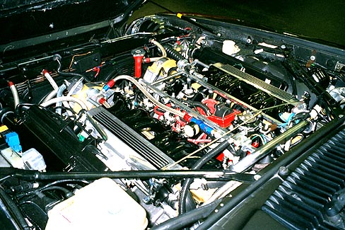
I feel that the engine is stunningly beautiful, and even more impressive
then the stock engine ever was. Everything is bright and shiny,
and I feel that the colors I chose really set off the engine.
One last little thing--that under hood heat padding from the factory
was getting old and tired looking.
J.C. Whitney . (800-529-4486) sells an effective,
and attractive, aluminium covered padding (#01RJ0705N)
that I glued to the underside of the
hood (#81RJ4606B). I used the original pad as a template,
and for neatness, used their
available Aluminium tape (#81RJ4607P)to cover up the edges. Everything was easily
cut with a pair of scissors. However, you will need two people
and four hands to fit this padding to the hood quickly and correctly. All in all,
a relatively inexpensive (about $35 USD) and easy to do mod that can
help make any car set off from the rest.
In conclusion, I'd have thought twice about doing this again,
but now that it is done, my XJ-S is even more a source of joy and
pride for me. If you choose to go this far, you are now forewarned!
But after almost 10 weeks of work, the results speak for themselves.
I am very happy with the way it turned out.
What do you think?
I'd appreciate you letting me know, so please let me know by signing my
Guestbook.
