God is in the details, or so the saying goes. So if
you are reading this, that means you are either interested in
installing these gauges or want to live vicariously through the
pain and suffering I went through to put them in!
Installation requires patience.
Like everything with this car, it is also time
consuming. And like anything, it's not hard once
you figure it out. I hope you can learn from my mistakes
instead of having to make them all over again on your own!
Let me start by talking about general installation steps,
then onto each gauge one at a time.
First step is to remove the trip computer. This is easy. Using a small,
dull flat head screwdriver, carefully pry away the vaneer for the
switches on each side of the unit--they push into the dashboard by some mounting
studs and holes in the facia. Once removed, you can slip your fingers behind the trip
computer and give it a gentle but firm tug outward. It is held in the dash
by spring clips on the side of the unit. Unplug the two cables connectors
on the back. The larger connector is for all the trip computer info
from the engine, ECU, etc, and will not be used. The smaller is the power
for the old trip computer unit. Later, we'll tap into this to provide
DC power for lighting the gauges themselves.
The first major task is getting the gauges to mount to something!
First I made a template out of stiff cardboard and
a wood working friend of mine made a thin lamanated panel with three equa-distant
52mm holes (that is the diameter of each gauge). This provided a temporary means of
mounting the gauges to see how they would fit in the dash. There is just enough
depth behind the gauges to mount them. This is one thing I did not think about
before ordering, so I was lucky it worked out.
I then hired a local furniture shop to make me this
vaneered piece to fit this exact
size. I also gave him the vaneer panels for the switches
on each side. They needed to be refinished anyway, but especially, I wanted him
to match the vaneer type of pattern and coloring so it would look factory.
You can contact the shop I used and reference this application. They even
have the specs for the metal backplate template used to hold the Omori
gauges.
Call Wit Williams at 804-358-0010 of Classic Touch,
2906 West Clay Street, Richmond, VA USA. He has done this
work for me and knows exactly what needs to be done. Only thing
is coordinating the color of your wood.
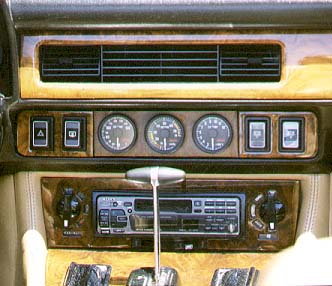
The template allowed me to decide the appearance/order of the gauges. Since the
vacuum has the most color on its face, I put it in the
middle and the Oil temperature
on the left and Manifold Temperature on the right.
Since each gauge has it's own seperate wire sheath, the next step was how
to get these wires into the engine compartment. Actually, Omori has designed
these gauges well. There are essentially up to three sections of
connections for each gauge:
- From the back of the gauge to under the dash (to be explained below)
- From the end of this into the engine compartment
- To the item to monitor
Getting this wiring from the engine compartment
into the cockpit is a bit of work. On my 1989 on
the passenger's (right) side at the firewall is a metal
bracket and a flex rubber hose that feeds connectors
through the firewall. I ran my connections
through this point. Unbolt the assembly for easier
access. Use of a rod (e.g. wire coat hanger) to "fish" the wiring through
is essential. I then ran it up under the glove box next to the
fuse panel. Removing the fuse panel cover makes this a
logical place to stage these connectors.
Getting the three snap in connectors
from the back of each of the three gauges down to
below the glove box is the first step. This is a very tight fit requiring
patient fishing of each cable. There is not a lot of room behind the
dash to get these wires down there. Take
out the right switch cluster, and the fuse box cover
below the glove box, and
you can see a little daylight down around where the passengers footwell is located.
I actually took a large flashlight so that I could
better see the route my wires needed
to take. Generally as I recall, I found it easier to push each wire strand
up from the bottom then to push them through from the dash downwards.
I used a coat hanger to pull it through in all cases--clearances
are too tight to hand feed.
The power for each gauge does not directly
tap in at the back of the gauge, but
at a small white connector for each wires gauge harness
(the end of which is now down by
the fuse box.) I then cut the power and ground
wires that formerly plugged into the
trip computer (the XXX and XXX colored wires
respectively), and fished
those down the same route as the other three harnesses.
I then spliced those into the
power connector in each harness. This is what lights up
the gauges at night. By the
way, the lighting is a really green illumination and the
backplates are translucent
for the numeric indicators. Very cool.
The second section of wiring for each gauge then has to connect to the end
of this first piece and go into the engine compartment. Fortunately, on LHD
cars there is a hole in the firewall on the right side of the firewall
(i.e. passenger side for LHD cars) for other connectors. Undo the metal bracket
to get better access to the real opening underneath. Then feed each connector
through the rubber 'nozzle' at the top of this unit where
the existing cabling is passing
through. It is a tight fit. I wound up tearing the aging rubber on this nozzle
by mistake. There is no way to repalce that without unterminating all
the other wires/harnesses, and that was way to much work and I just left it alone.
I used a coat hanger and some electrical tape to feed the ends down towards the
inside footwell. Omori's leads are long enough that you will have to coil the
remainder up by the firewall before connecting them to the engine. At this point,
rebolt down the bracket, and you are almost (but not quite) there.
Connecting each of the gauges requires a couple of things.
1) Oil Temperature Sensor
 The sensor end is supposed to go into the oil pan
through the drain plug. Omori provides a drain plug threaded in the
middle into which you can screw the sensor. Unfortuantely, the drain
plug provided is for smaller Japanese car engines and is too small
to fit the XJS's much more sunstantial drain plug. Get a new/used drain plug,
take it to a machine shop with the sensor that is supposed to screw through it,
and have them drill out a threaded hole for the temp
sensor to the correct thread size.
This job only cost $15 USD.
The sensor end is supposed to go into the oil pan
through the drain plug. Omori provides a drain plug threaded in the
middle into which you can screw the sensor. Unfortuantely, the drain
plug provided is for smaller Japanese car engines and is too small
to fit the XJS's much more sunstantial drain plug. Get a new/used drain plug,
take it to a machine shop with the sensor that is supposed to screw through it,
and have them drill out a threaded hole for the temp
sensor to the correct thread size.
This job only cost $15 USD.
2) Manifold Temperature Sensor
 This is perhaps the most
labor intensive of all. This sensor requires it's sensor to be in
the exhaust manifold downtube and there requires drilling into either the
manifold itself or a down tube. I have not connected this yet, but I have
bought a pair of used exhaust manifolds and will be
getting them ExtrudeHone'd, then high temperature coated to hold in heat.
Then I will get a machine shop to tap that hole for the sensor. Same routine
as before--take the sensor in with the part for precise fitting.
Of course the hard part is removing the original manifolds and installing
the new ones. Like anything on this car, it most likely is not as easy as
it sounds!
This is perhaps the most
labor intensive of all. This sensor requires it's sensor to be in
the exhaust manifold downtube and there requires drilling into either the
manifold itself or a down tube. I have not connected this yet, but I have
bought a pair of used exhaust manifolds and will be
getting them ExtrudeHone'd, then high temperature coated to hold in heat.
Then I will get a machine shop to tap that hole for the sensor. Same routine
as before--take the sensor in with the part for precise fitting.
Of course the hard part is removing the original manifolds and installing
the new ones. Like anything on this car, it most likely is not as easy as
it sounds!
3) Vacuum Connection
 This is the easiest of all. Go to an auto parts
store and by a tee vacuum line connection. I
attached mine to the back of the right intake
manifold (where four other vac connections are). The connector from the back
of the gauge to the manifold is a soft rubber tube, not a sensor wire
(however the gauge does have a power wire for lighting--see above). This
tube will snap over the connector at the back of the gauge and connect into the
the tee connection just added to the back of the manifold.
This is the easiest of all. Go to an auto parts
store and by a tee vacuum line connection. I
attached mine to the back of the right intake
manifold (where four other vac connections are). The connector from the back
of the gauge to the manifold is a soft rubber tube, not a sensor wire
(however the gauge does have a power wire for lighting--see above). This
tube will snap over the connector at the back of the gauge and connect into the
the tee connection just added to the back of the manifold.
To finish off the job--I cheated. I used foam carpet insulation and stuffed it in
the orrifice of the dash to hold the gauge cluster snugly in place.
So far so good.
It's ameturish, but looks great and it works. I tried in
vein to figure out a way to "pull"
the cluster in from behind, but could not.
There were some ugly gaps however that I wanted to cover. One was above
the entire gauge and left/right switches, and the other were the
two vertical gaps on each side of the new gauge cluster between the
(now) three vaneer surfaces. Again, simple answers are the best. My
local Pep Boys (auto parts) sells some black door molding that was perfect
for what I needed. Now it all looks "factory".
The results are more information about what the engine is doing and, I feel,
a much better looking dash board. Personally, I do not miss my old
ugly looking and often inaccurate trip computer, and am enjoying the
more sports car cockpit look of the interior too. The next step is
to replace those ugly rectangular push button switches with some lighted
rocker switches. More on that to follow!
